StressCrete
StressCrete proudly manufactures the broadest, most diverse range of made-to-order prestressed spun concrete poles.
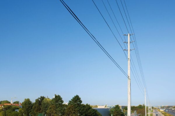
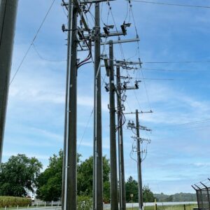
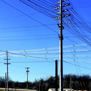
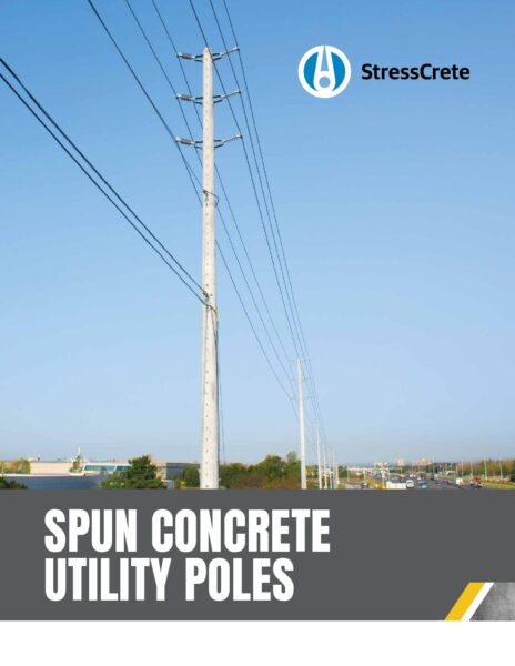
StressCrete spun concrete poles are durable and reliable, making them the ideal poles for power distribution and transmission.
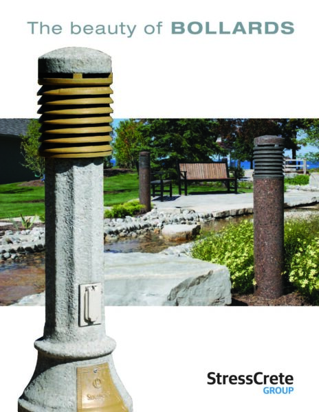
StressCrete produces a range of concrete bollards specifically designed to complement our poles.
StressCrete, established in 1953, is the oldest and most experienced manufacturer of spun concrete poles in North America operating from three facilities strategically located in Alabama, Kansas, and Ontario. From here, we serve customers across the continent with the broadest, most diverse range of made-to-order prestressed spun concrete poles.
We believe form and function should always coexist and that’s why every product we make is customized to meet the needs of our customers—from color, shape, length, and finish—all meeting our high standard for quality. We also stand behind our work—without question—and provide a lifetime warranty on every single one of our products.
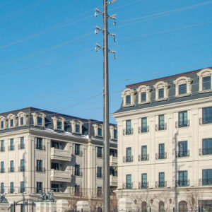
Expertly crafted and built to last, our concrete poles are designed to meet the demands of any project—whether it’s a residential pole paired with a decorative King Luminaire fixture or a utility pole strengthening your distribution system.
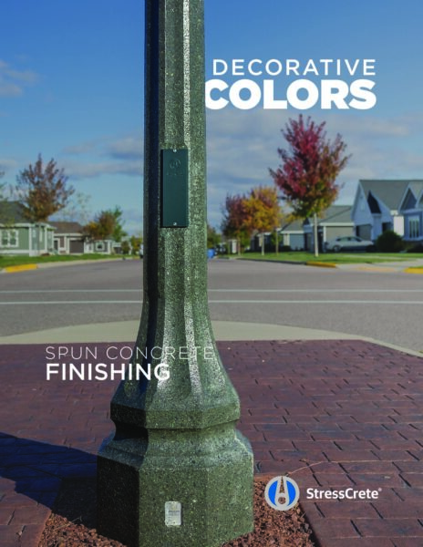
Centrifugally cast reinforced concrete poles, commonly known as spun poles, offer a unique blend of elegance and durability that outperforms most other materials in the industry. The spinning process imparts qualities to the concrete that are unattainable through conventional casting methods. This technique creates denser, stronger concrete while forming a hollow raceway inside the pole, providing a smooth conduit for electrical cables. Each StressCrete spun concrete pole is custom-made to meet the specific engineering requirements of our clients, ensuring a product tailored to their exact needs.
If you have a question that you cannot find answered here, please contact us.
Mounting Options
Direct Burial
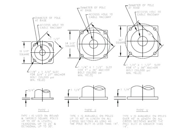
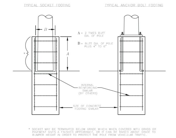
Spun concrete poles are generally direct buried eliminating the need for expensive anchor base footings. However, if required, base plate mounted poles can be supplied for most pole types. Under normal conditions, a concrete pole can be set “directly” into an augured hole, backfilling with the earth augured from the hole, tamping every 4” (10 cm). In situations where poles have large loadings, heavy imbalanced loads, or where soil bearing strengths are in question, an engineered base design may be required. In almost all cases the bases are less expensive than base plate mounted bases.
With the exception of extreme cases, all that may be required is a slight increase in bearing surface below grade. This can be achieved in a number of ways. The easiest is by simply setting the pole deeper, or by auguring a larger hole and backfilling with concrete or limestone screenings which are almost equal to concrete backfill when tamped damp in 4” layers and will allow easy removal if damage occurs to the pole.
Remember when in doubt call in an expert!
Results of StressCrete’s Direct Embedded Spun Concrete Poles
Time Savings
Installation takes time and time means money. Direct embedded poles can be installed in as little as one-half hour from start to finish, freeing the time of manpower and equipment.
Monetary Savings
It stands to reason that you can buy an extra few feet of pole for less money than it would take to design and build an anchor base. In some cases, the cost of the anchor base alone is equal to the total cost of a direct embedded concrete pole.
Visually Appealing
Direct embedment of concrete poles means no unsightly base plates to hide or nuts to cover. Pour concrete, lay asphalt or sod grass around the base of the pole. Our solutions provide a simple, neat, and cost-effective appearance.
Five Easy Steps to Follow to Ensure Proper Installation:
- Use the fish wire provided to pre-wire the pole, then install arms, luminaires, etc. while the pole is readily accessible.
- Auger the setting hole – minimum auger size should be 8” to 10” greater in diameter than the pole butt.
- Select backfill.
- To install, choke the pole with a nylon sling 20% to 25% of the pole length from the top, attach the sling to the hook, and lift allowing the butt to rest on the ground until vertical. Now lift the pole and position it over the augured hole and lower until the butt rests on the bottom center of the hole.
- While continuing to hold the pole, add backfill, tamping every 4”. Check for plumbness using a plumb bob or instrument, after which a below-grade wiring connection can be made. Remove the sling and move to the next pole while filling and tamping is continued to a point 2” above grade.
Base Plate Mounting
As an industry, we recognize there are a few occasions when various design criteria dictate the use of base plates despite cost disadvantages. We would be pleased to discuss your requirements for this type of pole, based on our experience of past installations.
Socket Mounting
A Viable & Economic Alternative to Base Plate Mounting
Socket mounting and base plate mounting are very similar. The footing size is the same and the internal reinforcing is similar; the major difference is that instead of anchor bolts, a socket is formed into the base. The pole is then set into the socket and grouted into place with non-shrink grout.
Advantages of Socket Mounting:
- Base cost savings – less concrete is needed, and expensive anchor bolts are not required.
- Easy installation – precision fit and lining up anchor bolts is not required.
- Pole cost savings – expensive base plate not required.
Pole Specifications
Pole Classifications
For almost all applications of spun concrete poles including street lighting, sports lighting, and power distribution, the theoretical load is applied near the pole tip; therefore, most poles are selected by tip load computation.
In order to simplify ordering and cataloguing, we have grouped our poles according to alphabetical classes, with a class being defined as minimum ultimate transverse load applied two feet down from the pole tip. All poles that can sustain the same tip load have the same class.
The ground line moment capacity depends on the pole length, since that moment is the product of the ultimate load and the distance between the point of application (2 ft. from the tip), and the ground line.
The table shown summarizes the concrete classes:
| Concrete Pole Class | Minimum Ultimate Transverse Load (lbs) | Minimum Ultimate Torque |
|---|---|---|
| A | 600 | 1100 |
| B | 900 | 1100 |
| C | 1200 | 2750 |
| D | 1500 | 2750 |
| E | 1900 | 2750 |
| F | 2400 | 2750 |
| G | 3000 | 5160 |
| H | 3700 | 5160 |
| J | 4500 | 5160 |
| K | 5400 | 8300 |
| L | 6400 | 8300 |
| M | 7500 | 8300 |
| N | 8700 | 12160 |
| O | 10000 | 12160 |
Pole Specifications
These specifications apply to the manufacturing of centrifugally cast, prestressed reinforced concrete poles (“spun concrete poles”). All spun concrete pole designs and wind loading calculations are prepared by an experienced licensed engineer.
Review the complete StressCrete concrete pole specifications here:
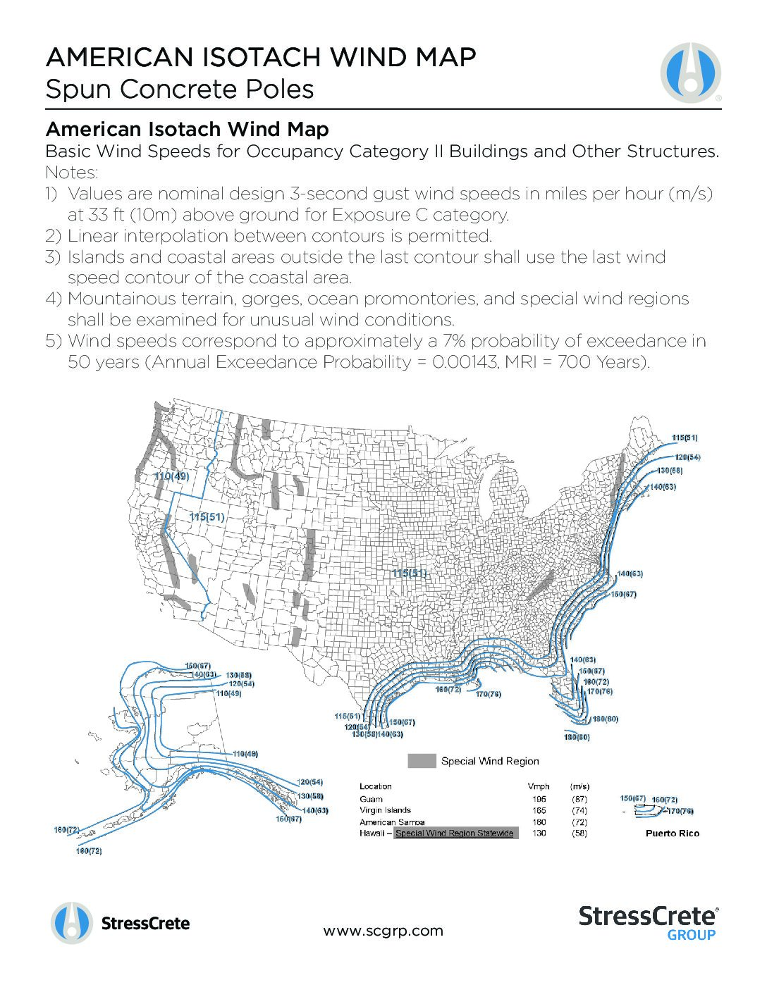
Isotach Wind Maps
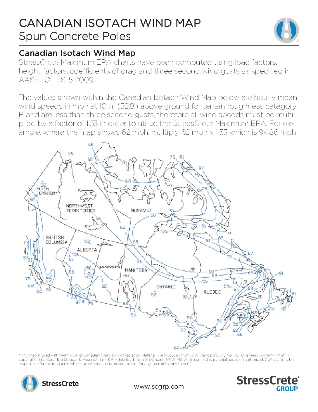
StressCrete references, among other things, the following Isotach Wind Maps for Canada and the United States of America when determining the loading requirements of our poles.
Review the Isotach Wind Maps for yourself here:
Standard Concrete Pole Features
Handhole Frames, Cover Plate, and Fasteners
Handholes are available in two standard sizes, based on the application. For all street lighting poles, the standard handhole size is 2-1/2” W x 8” H. For all sports lighting poles, the standard handhole size is 3-1/2” W x 10-1/2” H.
All handholes are box type, composed of non-metallic, non-conductive, injection molded material, or a 50,000 PSI high-density cast zinc ASTM ingot Spec # B669-82, and will be supplied with a close-fitting inset cover of the same material. All fasteners will be stainless steel.
On street lighting poles, the handhole will be located 18” above grade. On sports lighting poles, the handhole will be located 3’6” above grade. These dimensions can be easily adjusted to specific needs, within the design and physical limitation of the poles in question.
Fasteners
In the U.S.A., our standard fastener is a 1/4” – 20 x 3/4” Allen (Hex) pan head bolt – 3/4” long. In Canada, our standard fastener is 1/4” – 20 x 3/4” #3 Black Robertson square pan head bolt – 3/4” long.
Tamperproof fasteners are available upon request. Our standard is a 1/4” – 20 x 3/4” Allen (Hex) pan head with a raised pin in the center as manufactured by the Tamperproof Screw Company.
Wiring Apertures
Pole Top
Location will vary with application selected.
On street lighting poles, depending on the arm style selected, the top wiring access will either be through the top of the pole or through an opening in the side of the pole.
On sports lighting poles under 50’ above grade, a 1-1/2” coupling will be supplied for wiring access. A 1-1/2” x 3” aperture may be specified as an alternative. On poles 50’ above grade and over, a 2” coupling will be supplied with J hook wire hanger and a 2-1/2” x 8” handhole at 180° to the coupling at each platform/crossarm level.
Below Grade
Location of aperture is standard 18” below grade to center line of aperture unless otherwise specified.
On street light poles, twin 2-1/2” x 5” apertures at 0° and 180° to handhole is standard.
On sports light poles, a single 3” x 12” is standard on all poles less than 50’ above grade and 4” x 10” on all poles 50’ above grade and over. It will be located in line with handhole, unless otherwise specified.
Inserts
All inserts are zinc die cast or hot dip galvanized and available in 1/4”, 3/8”, 1/2”, 5/8”, and 3/4”.
Through Holes
Standard hole sizes are 1/2”, 3/4”, and 1” nominal size.
Electrical Grounding of Poles
Where electrical conductivity is concerned, a concrete pole is in essence a steel pole, thus we strongly recommend that it be grounded. The last letter “G” in the pole catalog number indicates that the pole will be supplied with a provision for electrical grounding. Standard Ground in Handhole and External Ground are two methods approved by the Canadian Standard Association (CSA).
Shipping & Handling
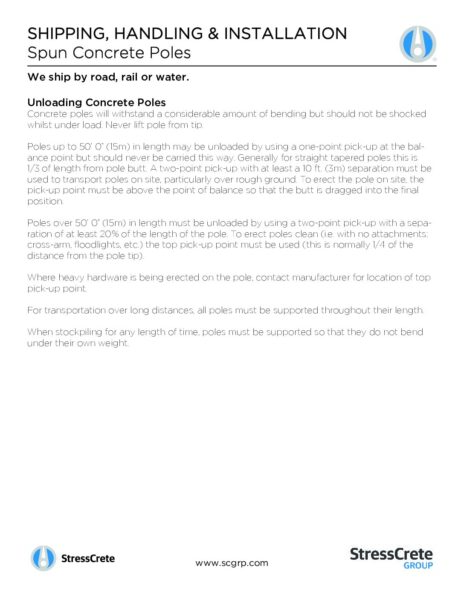
We ship by road, rail, or water.
Unloading and Storing Concrete Poles
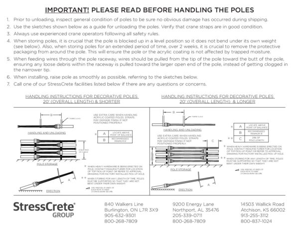
Concrete poles will withstand a considerable amount of bending but should not be shocked whilst under load. Never lift pole from tip.
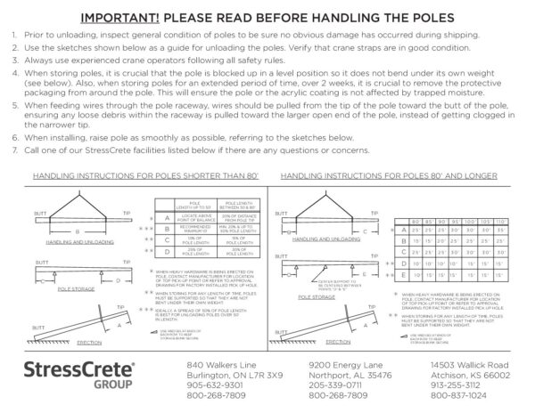
Poles up to 50’ 0” (15m) in length may be unloaded by using a one-point pick-up at the balance point but should never be carried this way. Generally, for straight tapered poles, this is 1/3 of length from pole butt. A two-point pick-up with at least a 10 ft. (3m) separation must be used to transport poles on site, particularly over rough ground. To erect the pole on site, the pick-up point must be above the point of balance so that the butt is dragged into the final position.
Poles over 50’ 0” (15m) in length must be unloaded by using a two-point pick-up with a separation of at least 20% of the length of the pole. To erect poles clean (i.e. with no attachments; cross-arm, floodlights, etc.), the top pick-up point must be used (this is normally 1/4 of the distance from the pole tip).
Where heavy hardware is being erected on the pole, contact manufacturer for location of top pick-up point.
For transportation over long distances, all poles must be supported throughout their length.
When stockpiling for any length of time, poles must be supported so that they do not bend under their own weight.
